If you do
NOT see the Table of Contents frame to the left of this page, then
Click here to open 'USArmyGermany'
frameset |
European Troposheric - Army
22nd Signal Group
Looking for more information from military/civilian
personnel assigned to or associated with the U.S. Army
in Germany from 1945 to 1989. If you have any
stories or thoughts on the subject, please contact me . .
|
|
|
|
|
|
| European Tropospheric-Army |
| |
European Troposheric - Army - ITT Report, 1968 (Charles Cox)
(PDF File; size = 7 MB; requires Adobe Acrobat viewer) |
| |
|
| |
| (Source: TM 11-5895-376-14-1,Operator's, Organizational, Direct Support and General Support Maintenance Manual, ET-A Mainline Site, Aug 1976 ) |
ET-A Microwave Communication System
The ET-A mircowave communication system provides a complete long-haul microwave network in the European area. The system consists of two basic types of site configurations, mainline sites and tributary sites.
(1) Mainline Sites: these are sites along the primary broadband multichannel radio network.
(2) Tributary Sites: these are remote stations requiring only single- or two-channel special purpose communications.
Mainline Sites. The mainline sites form important links in the primary radio network. Much of the radio equipment used at mainline sites contains cabling for future equipment additions. Since traffic loads and site functions differ along the mainline route of communication, the size and complexity of the sites vary considerably. Mainline sites may vary in size from an ordinary repeater station to a fully implemented nodal point station or console site (see Mainline Site Configurations below).
Tributary Sites. Tributary sites are remote stations which are serviced by the mainline of the ET-A system. Tributary sites are connected to the mainline through nodal point sites.
ET-A Console System. The ET-A Console System is a command and control facility incorporated within the ET-A microwave communication system. It uses the radio and multiplex equipment of the ET-A microwave communication system to provide semi-automatic conference call capabilities between the local telephone sets (drop subsets) at various headquarters locations (Console Operations Centers) and a large number of military installations (tributary sites). Basically, the Console System consists of six Console Operations Center sites and a number of Console Remote Equipment (CRE) vans. A Console Operations Center is linked to a CRE van via the radio and multiplex equipment along the mainline. (Five mainline "command and control" channels are used for this purpose.) The CRE vans are located at the mainline nodal sites, each van being equipped to service a maximum of 24 tributary sites.
MAINLINE SITE CONFIGURATIONS
1. General
 a.
The equipment complements at mainline sites vary and depend on the operational requirements of each specific mainline site. However, all mainline sites fully or partially fall into one of the following six basic configurations: a.
The equipment complements at mainline sites vary and depend on the operational requirements of each specific mainline site. However, all mainline sites fully or partially fall into one of the following six basic configurations:
Through repeater site
Drop repeater site
Terminal Site
Junction Site
Nodal point site
Console site
The six configurations are discussed in paragraph 3 through 8.
b. In addition to basic configuration variations, the radio equipment complement varies due to different microwave transmission modes. Mode variations are described in paragraph 2.
2. Diversity and Modes of Operation
The sites on the mainline broadband network of the ET-A system use the troposcatter, diffraction or line-of-site mode of microwave transmission; four-fold or two-fold space diversity configurations are utilized.
a. Troposcatter. In the troposcatter mode of operation the radio equipment required to meet system performance requirements consists of either 1-kw or 10-kw transmitters, receivers with or without parametric amplifiers and treshold extension, 15 or 30-foot antennas, and four-fold space diversity. The four-fold space diversity configuration uses two antennas, two transmitters, and four receivers (two dual receivers).
b. Diffraction. In the diffraction mode of operation
the radio equipment required to meet system peformance requirements consists of 1-kw transmitters, receivers with parametric amplifiers and threshold extension, 30-foot antennas, and four-fold space diversity (see a above). Only one mainline link (Site 11.1, Feldberg/Schwarzwald, to Site 46, Savona, Italy) operates in this mode.
c. Line-of-Sight. In the line-of-site (LOS) mode of operation the radio equipment required to meet system performance requirements consists of 1-watt transmitters, receivers without parametric amplifiers and treshold extension, 4 or 6-foot antennas, and two-fold space diversity. The two-fold space diversity configuration uses two antennas, two transmitters, and two receivers.
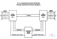
3. Through Repeater Site
a. The through repeater site is usually located in a high-elevation area for the purpose of linking two mainline sites between which direct communication in the troposcatter mode is not feasible. The through repeater receives the microwave signal from one site, amplifies it, and transmits it to the next site. A block diagram of a through repeater site is shown in figure 2.
b. The through repeater site equipment complement consist of two radio shelters, each of which is connected to an antenna system and a maintenance control center (MCC) console. The antenna systems are pointed toward the neighboring mainline site antenna system, while the radio shelters are connected back-to-back at the multiplex baseline level. The orderwire channel from each direction is dropped to voice frequency in its corresponding radio shelter and extended to the MCC. In each radio shelter, only the orderwire channel in the direction of the shelter's shoot may be utilized. At the MCC, however, the orderwire channels may be utilized in either direction, or may be connected as a through circuit in both directions for conference purposes. Summary fault alarm circuits are extended from both radio equipment shelters to the MCC, permitting monitoring of the equipment from one location and eliminating the requirement that personnel be in the radio equipment shelter continually.
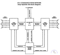
4. Drop Repeater Site
a. The purpose of the drop repeater site is to divert a limited number of multiplex channels from the microwave signal for local use. A block diagram of a drop repeater site is shown in figure 3.
b. The drop repeater site equipment complement consists of two radio equipment shelters, a multiplexer set, and a maintenance control center console. The antenna systems are pointed toward the neighboring mainline site antenna system. Each radio equipment shelter feeds its multiplex baseband output to the multiplexer set. The multiplexer set processes the baseband from one direction, dropping a limited number of channels to voice frequency level for local subscriber use. The remaining channels are passed to the other baseband, at either channel, group, or supergroup level, for transmission to the next site.
c. Orderwire channels from each direction are dropped to voice frequency in the radio equipment shelter and extended to the MCC. Each radio shelter may use the orderwire channel in the direction of the shelter's shoot only. However, at the MCC the orderwire channels may be used in either direction or may be connected as a through circuit in both directions for conference purposes. The MCC also extends a local orderwire circuit to the multiplexer set, which can also be connected into the conference circuit.
d. Summary fault alarm circuits are extended from both radio equipment shelters and the multiplexer set to the MCC, permitting monitoring of the site equipment at the MCC without requiring personnel be in the radio equipment and multiplexer set shelters continually.
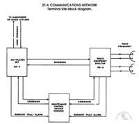
5. Terminal Site
a. Terminal sites are located at each end point of the ET-A mainline, where all multiplex channels are dropped for local subscriber use or interface with other systems. A block diagram of a terminal site is shown in figure 4.
b. The terminal site equipment complement consists of either one or two radio equipment shelters, a multiplexer set, and a maintenance control center console. The terminal site shown in figure 4 utilizes one radio equipment shelter.
c. The radio equipment shelter is connected to an antenna system which is pointed toward the next site on the mainline. From the radio equipment shelter the baseband is fed to the multiplexer set, where all channels are dropped to either supergroup, group, or channel level for either local subscriber use or interface with other systems.
d. Orderwire channels and summary fault alarm circuits are utilized as described in paragraphs 4c and 4d, respectively.
6. Junction Site
a. A junction site serves as a junction for the mainline paths converging on the junction from three or more directions (sites). A junction site block diagram is shown in figure 5.
b. The junction site equipment complement consists of a technical control van, two or more multiplexer sets, three or more radio equipment shelters, and a maintenance control center console.
c. The junction site shown in figure 5 utilizes two multiplexer sets and three radio equipment shelters. Each radio equipment shelter is connected to its antenna system, which is pointed toward another site; thus three paths are converging on the junction site. Radio equipment shelters RS A and RS B feed their baseband outputs to multiplexer set MS A, while radio equipment shelter RS C feeds its baseband to multiplexer set MS B. The mulitplexer sets drop the three basebands down to channel voice frequency level. All channels are then routed to the technical control van. The technical control van contains a main distributing frame for cross-connecting the voice-frequency channels, in any of the three radio-frequency directions, to other systems or to local subscribers. Jack fields are also provided for patching or monitoring all channels.
d. Orderwire channels and summary fault alarm circuits are utilized as described in paragraphs 4c and 4d, respectively.
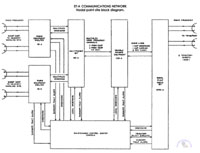
6. Nodal Point Site
a. A nodal point site serves as a junction for connecting the tributary sites to the mainline communications network. A nodal point site block diagram is shown in figure 6.
b. The nodal point site equipment complement consists of one to three nodal point radio sets, one Console Remote Equipment van, a multiplexer set, and one (terminal) or two (repeater) radio equipment shelters.
c. The nodal point site shown in figure 6 utilizes one nodal radio and two radio equipment shelters. The two radio equipment shelters and the mulitplexer set are set up as a through repeater site, as described in paragraph 3. The multiplexer set drops five command and control multiplex channels (used throughout the ET-A Console System) to voice-frequency level and feeds them to the CRE van.
d. The CRE van can service as many as three sectors of up to eight tributaries each, a nodal point radio set being required for each sector. Therefore, as many as three nodal point radio sets can be connected to the CRE van. Operation of the CRE van is automatic and is controlled by signals from either a Console (site,) Operations Center or a tributary site. The command and control channels () carry controlling signals and traffic from the console sites and other tributaries. The five channels from each direction of the mainline are bridged in the CRE van, thus giving the switching circuits of the CRE van uninterrupted connection to the mainline in both directions. From the CRE van one transmit oderwire, one transmit carrier channel, and eight receive channels are fed to the nodal point radio set, which feeds a pair of antennas pointing in the direction of a tributary site. Eight tributary sites can be so connected by eight antenna pairs.
e. The CRE van, on receiving a command from a Console Operations Center (to) a tributary site on one of the command and control channels, connects that channel of the transmit channels to the nodal point radio set. The nodal point radio set then transmits the data to all equipped tributaries. Traffic from a tributary is sent to the nodal point radio set and then to the CRE van on the tributary receive channel (??) to that tributary. The CRE van connects the traffic received from the tributary (to one) of the command and control channels for transmission, via the mulitplexer set () radio equipment shelter, to the other tributary or to the Console Operations Center.
f. Orderwire operation at the radio equipment shelters and multiplexer is the same as described in paragraph 4c. Service is also extended from the MCC to the CRE van and the nodal point radio set. Select controls are provided at the (CRE) and nodal point radio set for selecting the orderwire channel to any one of the (eight) tributaries. The MCC van can also connect the mainline orderwire with the tributary orderwire.
g. Summary fault alarm circuits are extended from all shelters and vans to the MCC, thus permitting monitoring of the equipment at the MCC without requiring personnel to be at the shelters and vans continuously.
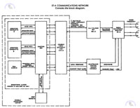
7. Console Site
a. The console site provides central control capability within the command and control network of the ET-A system. A block diagram of a console site is shown in figure 7.
b. The console site equipment complement consists of a Console Local Equipment van, an Operations Center (in building or van), a multiplexer set, one or two radio equipment shelters, a maintenance control center, and telephone drop subsets.
c. The Console Operations Center equipment (which includes the Operations Center and CLE van) may be used with the drop repeater configuration or the terminal configuration. The block diagram shown in figure 7 utilizes the terminal configuration. From the multiplexer set the five multiplex voice frequency channels, which are assigned command and control channels in the ET-A Console System, are routed to the CLE van for processing.
d. The CLE van contains the logic and signaling circuitry that performs the following functions:
|
(1) Receives status data from all tributaries and other console sites and converts the data into signal for the wall display. The wall display, therefore, provides a centralized display of the status of all system users. |
|
|
|
(2) Responds to commands initiated by the in-control operators consolette to establish communication with any or all the tributary sites and local drop subsets within the ET-A Console System. |
e. The orderwire operation is the same as described in paragraph 5, with service also extended to the CLE van.
f. Summary fault alarm circuits are extended from all shelters and vans to the MCC, permitting monitoring of the console site equipment from one point.
|
|
|
|
|
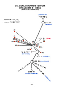
1. Mainline Site 8.1 (Stein) (KB)
|
2. Through repeater site (KB) |
3. Drop repeater site (KB)
|
|
4. Terminal site (KB) |

5. Junction site (KB) |
6. Nodal point site (KB)
|
|
7. Console site (KB) |
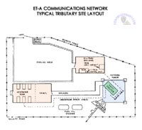
8. Typical Tributary Site Layout (KB) |
|
|
|
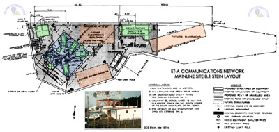 6. Site 8.1 (Stein) Layout - early phase (see Bob Brewer's comments about the changes to the layout)
 |
|
. |
|
|
| |
| (Source: SIGNAL, September 1966) |
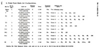 ET-A Nodal Points
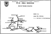
ET/A and 486L MEDCOM
Tropo Networks, 1966 |
|
A major segment of the Department of Defense communications network in Europe was activated July 19 (1966). The new system went into operation as part of the ET-A ( European Tropo-Army ) network that spans a number of nations in Western Europe. The system ties in communications from Leghorn, Italy, through the Italian Alps to Bremerhaven, Germany, and from Heidelberg to within a few miles of Paris, adding more than 1,200 channel miles to the US Army Strategic Communications Command’s world-wide communications complex.
Subsequent phases will expand the network. In addition to connecting with STRATCOM’s global network, the system will support US Forces in Europe and NATO Armies. The communications equipment used in the system was designed and is being manufactured and installed by the International Telephone and Telegraph Federal Laboratories. |
|
| |
MISCELLANEOUS INFORMATION
(Source: TM 11-5820-758-15, October 1968)
AN/MRC-114 - Nodal Point Radio Set
Nodal point radio sets were used to connect remotely located military installations (tributary sites) to other remotely located military installations and up to six command locations served by the main line of communications in the European Tropospheric Scatter-Army (ET-A) network. The nodal point radio sets, located at mainline nodal point sites, each serve a sector of tributary sites in the nodal-to-tributary-site direction. Up to eight tributary sites can compose a sector. Either tropospheric scatter or line-of-sight transmission may be used for the radio links between the nodal points and the tributary sites.
Because of differences in the number of tributary sites being served and differences in distances and terrain characteristics between nodal points, different radio set van configurations are used. The configurations and their specific use in the ET-A system are given in the 'ET-A Nodal points' table above.
The manual goes on to identify two of the nodal sites: |
SITE |
LOCATION |
COMMENTS |
| Nodal Site 9.1 |
Donnersberg |
serves three tributary sites |
| Nodal Site 50.1 |
Hohenstadt |
serves two tributary sites |
|
|
| |
| Early 1970 |
| (Source: Email from Bob Brewer) |
Interesting site you have. I served a couple of years at 8.1 in the early 70's. Drove through the area on vacation a couple of years ago. Tower was still there but Army portion of site demolished. Satellite obviously killed need for networks like this. Looked like it was being used by local cell phone.
Re your chart of tropo radio sites: |
SITE |
LOCATION |
COMMENTS |
| Nodal Site 7 |
Schoenfeld |
|
| Nodal Site 8.1 |
Stein |
|
| Nodal Site 9.1 |
Donnersberg |
|
| Nodal Site 11 |
(still unidentifed) |
|
| Nodal Site 11.1 |
Feldberg/Schwarzwald |
|
| Nodal Site 50.1 |
Hohenstadt |
|
| Nodal Site 51.1 |
Linderhofe |
|
| Nodal Site 52 |
Bremerhaven |
|
|
| |
ADDITIONAL INFORMATION
My time at 8.1 was primarily as a maint tech on the data links to the telephone sets at the trib sites but I did some work on the radios. I have an old map that lists theoretical trib sites as the net was originally planned to be built out. I know 8.1 had more sites listed on the map than we ever actually operated as of 1972. Don't know if the full network was ever built out or satellite overtook the tropo technology.
The European Command Control Console System (ECCCS) was basically a private telephone network that connected nuclear warhead sites in Europe to Botley Hill outside London for eventual hookup to US. I think this net used only a portion of the European tropo radios as I know that there were Autovon/Autodin radio sites that my net had no direct contact with.
(Re: posting of Mainline Site information from TM-11-5895-376-14-1) . . . Absolutely fascinating stuff. I hadn't thought about a lot of this for years but this certainly brings back a lot of memories. I was surprised at how much of this old tech stuff is online.
|
|
|
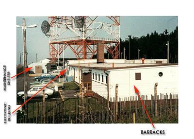
Interesting that the manual you found had 8.1 as the sample site, though the site map turned out not to be correct. The picture you've pasted in is looking in the main gate toward the east. The Quonset hut type building in the rear left of the picture is the one described as Maintenance Shelter on the site map. As you can see the projected fence line has been moved quite a ways west. The slightly taller portion to the rear of the new building is the actual "Projected Electronic Building" and directly attached to it in the foreground is the actual "Future Barracks."
The generator building as shown existed in that spot but nothing else was ever built in the oddly shaped area to the east. Probably because that land sloped downhill - it would have been a more difficult construction and vehicle access from the gate would have been more of a problem. The comm equipment was in vans at the base of the tower pretty much as shown, tho in late 1972 the vans were stripped and the equipment moved into a permanent installation in the Electronic section of the new building.
|
|
A couple more numbers for your map - 44 was Heidelberg and 8 was Feldberg/Taunus to differentiate from Feldberg/Schwarzwald. 14.1 might have been Koenigstuhl - it had a shot from Donnersberg but I'm not positive that was the number.
One last tidbit of info - one the mainline site configurations section talking about diffraction mode transmission - Site 46 was Savona Italy. |
SITE |
LOCATION |
COMMENTS |
| Mainline Site 8 |
Feldberg/Taunus |
|
| Mainline Site 44 |
Heidelberg |
|
| Mainline Site 46 |
Savona, Italy |
|
|
| |
The building you mention is what shows on the diagram as Generator Shelter, though "power building" might be a better name. The site had dual redundant feeds from separate sections of the German power grid, a flywheel driven no-break generator large enough to hold up the entire site plus two other standby generators each of which was large enough to hold up the entire site. Basically five independent sources would have to fail simultaneously to take the station off the air.
In looking closer at your picture, however, I'm not sure what is behind the barracks, sort of opposite the chimney. It looks like it could be an equipment van of some kind - if this pic is from late 70's that might be early satellite radios, since the electronic building was full with the terrestrial stuff.
I was reading your post from Terry Allan - it seems the original maintenance building was turned into a garage and the CRE remained in a van even after the radios and mux were put inside the building.
At the time I was in the area we were all parts of Co B, 360 Sig Bn. |
|
|
| 1982 |
| (Source: Email from Mark Ingman) |
The image on this page shows station 8.1, Stein b. Neukirch, and brought back some memories.
I recognized the antenna & building immediately and I think I even know the name of the owner of the silver Sirocco parked in the first spot, Peter Zensen (a German civilian), assuming the details are accurate.
OTOH, I was there as a microwave repairman from 1982 to 1985, but the other vehicles appear a bit older so not sure of the date. (I was assigned to the 532nd Signal Company in Gießen, 39th Signal Battalion.)
When I arrived, the green trailer parked next to the end of the building in about the middle of the photo was actually the replacement for another CRE, one which, as I understood it, was supposed to have been stationed in France but was withdrawn when the French refused having nukes.
However, while I was stationed there I believe that the equipment in the trailer was moved inside the building and then the trailer was moved to other CRE stations to allow the other stations to remain on the air while some grades were being performed.
Also, during my time, the building marked as maintenance shelter had actually been turned into a theater. We would get films in from geeson and would be able to watch them back there.
I think the generator building was directly behind the electronics building and I believe there was also a garage or some other vehicle maintenance area behind the labeled maintenance shed.
Pack rat that I am, I believe I still have some of the technical documentation for how the site operated, but it's buried pretty deeply. As I'm looking at the photo and contemplating my time there, the memories are slowly starting to come back.
I'm not sure why I never thought about searching for this stuff online before now.
ADDITIONAL INFORMATION
If that was Peter's Sirocco, then it might be my green Buick Century parked just next to him (hidden), but the image isn't really clear enough to tell.
I am fairly confident about the trailer parked next to the technical room; it was the CRE from France, some or all of it was in that trailer for a long time, and the equipment was eventually moved into the building and the trailer then removed to be used at some other CRE as a temporary technical structure while the building was being renovated.
I am also fairly confident about the quonset hut. I believe before my time it was a maintenance shelter but when I was there it had been turned into a movie room. I think it wasn't used too much because it was often cold and the heat took a long time to work (the heating fuel even froze once) and we were also by then receiving video tapes to watch in the main building. (The 'We Are The World' video came out while I was there, as well as a lot of Michael Jackson.)
Behind the quonset hut (maybe part of the same building) was a small hobby garage where we could work on our cars.
The long roofline visible in the background was the generator building.
There was one main motor/generator/flywheel/diesel setup which was usually driven by commercial power, but when there was a voltage drop or power loss, that diesel would start up while the flywheel kept the power going.
There were also 3 other 200kW generator sets ready. If power went down, two of the three would start up, with one going online and the other running unloaded as backup.
These generators were started with compressed air, and there were 3 large compressed air storage tanks in the building.
The UPS system I believe used 24V starter batteries, and I know there was a large bank of 24 or 48v batteries but I'm not clear on their use. We didn't have any DCO stuff but we did have a multiplexer or two, I believe it carried telephone traffic for the US military telephone system in Europe. Maybe the battery banks were to provide DC power for the muxes.
When I was there, our company HQ was in Gießen and we had a VW van as a site vehicle.
Before my time there they had a Chrysler van which was apparently replaced because someone bombed past a big-wig doing over 100mph on the Autobahn in it. The VW obviously wasn't going to be that capable.
I am still in contact with a German friend, Frank Warkus, who I met at CRE school in Mannheim (5th Sig Command) and who worked at Linderhofe (51.1). I have forwarded him the link. He may be able to improve memory accuracy. |
 |
|
|
| List of ET-A Sites |
| |
| |
Mainline Sites |
Site # |
Operating Unit |
|
|
Bremerhaven |
52 |
|
|
|
Donnersberg |
9.1 |
|
|
|
Feldberg |
8 |
|
|
|
Feldberg-Schwarzwald |
11.1 |
|
|
|
Heidelberg |
44 |
|
|
|
Hohenstadt |
50.1 |
|
|
|
Linderhofe |
51.1 |
|
|
|
Munich |
|
|
|
|
Schoenfeld |
7 |
|
|
|
Stein |
8.1 |
|
|
|
|
|
|
|
|
Bussac, Fr. |
|
|
|
|
CDL |
|
|
|
|
Dreux, Fr. |
|
|
|
|
Flobecq, Bel. |
|
|
|
|
Gorramendi, Spain |
|
|
|
|
Maison Fort , Fr. |
|
|
|
|
Nancy, Fr. |
|
|
|
|
Vatry, Fr. |
|
|
|
|
|
|
|
|
|
Savona, It. |
46 |
|
|
|
|
|
|
|
|
(list still incomplete) |
|
|
|
|
|
|
|
|
|
|
| |
LOCATION of other ET-A sites:
Maison Fort, France (prior to FRELOC)
STRATCOM Facility, Saran, France (prior to FRELOC)
STRATCOM French Regional Command (prior to FRELOC)
ET-A Trib Site, Hemer-Menden, 1967
ET-A Trib Site, Baden-Söllingen, 1965
ET-A Site, Hanau, 1969
|
| Can anybody provide additional details on the ET-A Network? |
| |
| Click here for some additional information on the ET-A network |
|
|
|
| Equipment General Support Maintenance Company |
| |
| (Source: STARS & STRIPES, March 13, 1967) |
The Equipment GS Maintenance Company (a Com Z unit) was activated on June 25, 1966 at the US Army General Depot, Kaiserslautern. The mission of the Company is to provide maintenance support to the ET-A sites throughout Western Europe.
In March 1967, a 51-man detachment was sent to Kassel (Rothwesten Air Base?). This relocation is the first phase of a plan to divide the company into several detachments that will be stationed at the following locations:
Kassel
Ulm
Recklinghausen
Bremerhaven
Italy
(Webmaster Note: STATION LIST, 30 June 1968, indicates that this company is stationed at Daenner Kaserne, Kaiserslautern, and is an element of General Depot, Kaiserslautern, APO 09054) |
|
| |
MISCELLANEOUS INFORMATION:
"C" Det, EGSM Company, was located at Nelson Barracks, Neu Ulm, in the early 1970s. They provided signal support for microwave and other signal sites in southern Germany. |
|
|
| |
Related Links:
|
| |
| |
|